52 |
Oilfield Technology
September
2016
Production logging (PL) and other commonly used technologies for
well profiling require stopping and restarting well productionmultiple
times, pumping fluids into the well as the PL tools are run into the well,
andmoving the PL tools along the wellbore.
Distributed sensing has the advantage in that fibre-optic cable based
measurements are completely passive and do not effect downhole
conditions. Depending on the fibre-optic application, the entire wellbore
can be profiled without cablemovement. If the fibre is permanently
installed in the wellbore when a distributed sensing survey is desired,
an interrogator is connected to the fibre on surface and the survey is run
without impacting production.
Because distributed sensingmethods are passive they do not require
cablemovement, the surveys are less risky and aremore representative
of ‘normal’ well conditions, and hencemore accurate than PL surveys.
The advantage of distributed sensing is that it provides both steady state
production profiles as well as dynamic wellbore effects associated with
shutting in and restarting production.
Running fibre into the well inside an intervention string can have a
minor impact on flow dynamics in the wellbore because of the reduced
flow aperture of the wellbore while the intervention string is in place,
however, the flow aperture is reduced uniformly throughout the wellbore
provided the coiled tubing string is run to the toe of the wellbore.
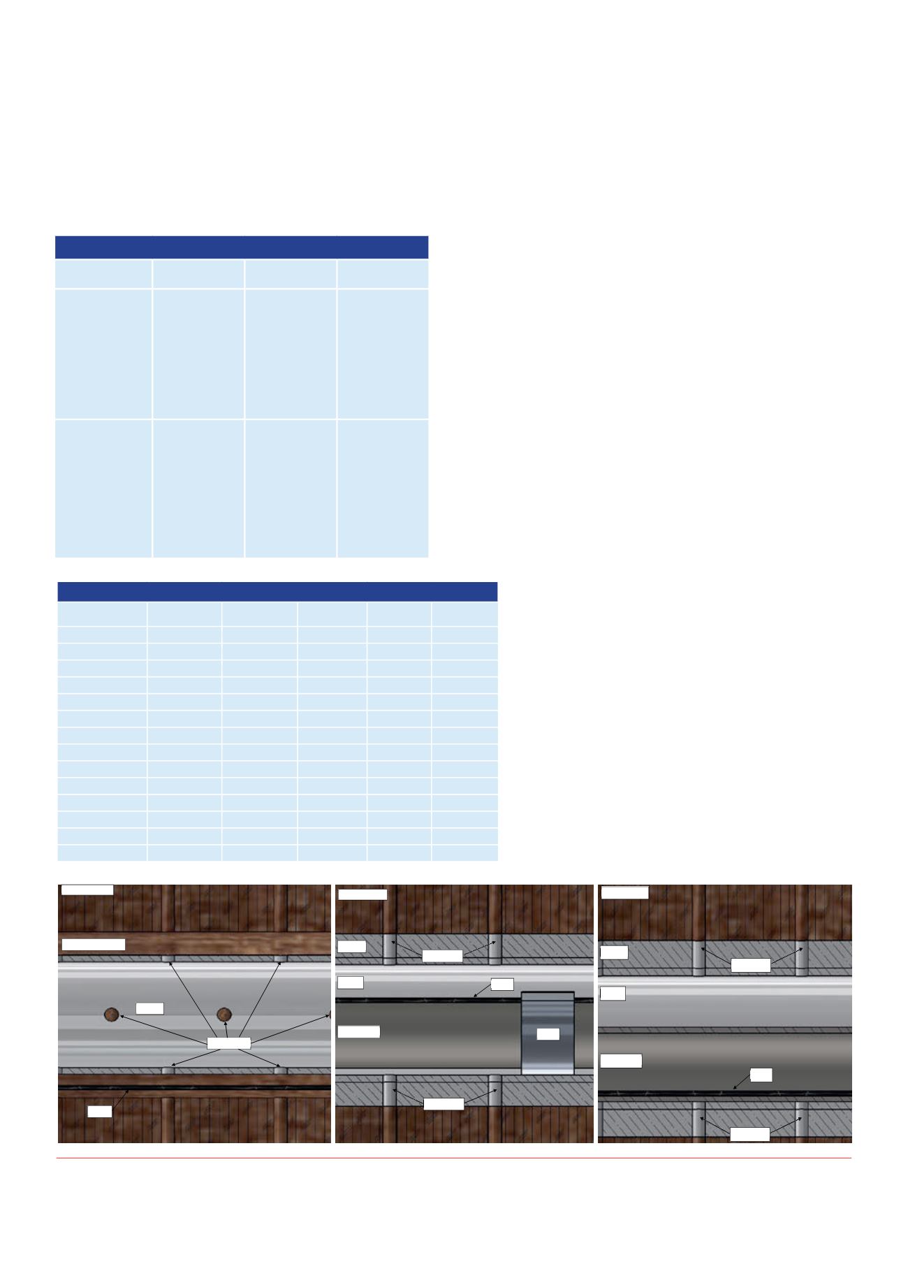
Fibre-opticcabledeployment
Fibre-optic cable can be deployed into thewellbore on the outside of the
casingwhen thewell is drilled as illustrated in Figure 1 (Left), strapped to
the outside of the production tubingwhen thewell is completed as shown
in Figure 1 (Centre), ormerely inserted into thewellbore periodically for
distributed sensing surveys, shown in Figure 1 (Right). Coiled tubing is
typically used to convey the fibre-optic cable into thewellbore for short
surveys. Fibre-optic cable can also be conveyed into thewellbore using
commonwireline techniques. Carbon-fibre rods containing fibre-optic
cables have been used for distributed sensing surveyswith some success
in theNorth Sea.
Deciding which avenue to deploy fibre into the wellbore is most
suitable depends on a number of circumstances. Some advantages and
disadvantages of the various deployment strategies are shown
in Table 1.
For economic reasons, less than 1%of newwellbores have
fibre-optic cable permanently installed as part of the completion
when they are drilled. A higher percentage of SAGDwells have
fibre strapped to production or injection strings that are hung off
in the wellbore as part of the completion process than other well
types but the numbers of these semi-permanent installations are
still relatively few. Running an intervention string such as coiled
tubing that contains fibre-optic cable is themost cost-effective
method to performDTS surveys.
DownholeDTSapplications
Productionprofiling
DTS is cost comparative to conventional production logging
techniques that rely on spinners and other instrumentation
Figure 1.
(Left) Cross section of fibre install. (Centre) Cross section of FIMT strapped into production tubing. (Right) Cross section of fibre inside coiled
tubing intervention string.
Figure1–Crosssectionofpermanentfiberinstall
FormationRock
Open hole wellbore
Casing
Perforations
FIMT
Figure2–CrosssectionofFIMTstrappedtoproductiontubing
FormationRock
Casing
Cement
Perforations
FIMT
CoiledTubing
Strap
Perforations
Figure3–Crosssectionoffiberinsidecoiledtubinginterventionstring
Decidingwhichavenuetodeployfiberintothewellboreismostsuitabledependsonanumberof
circumstances.Someadvantagesanddisadvantagesofthevariousdeploymentstrategiesareshownin
Table1.
Table1-Advantagesanddisadvantagesoffiberdeploymenttechniques
Fiberinstalledoutside
Fiberstrappedto
Fiberconveyedinside
Perforations
Perforations
FormationRock
Casing
Cement
FIMT
CoiledTubing
Table 1. Advantages and disadvantages of fibre deployment techniques.
Fibre installed outside
casing
Fibre strapped to
production tubing
Fibre conveyed inside
coiled tubing
Advantages
- Least invasive
measurements.
- Can be used during
well stimulation.
- Can be used with
DAS for microseismic
surveys.
- Fairly noninvasive
measurements.
- Can be used to
determine the fluid
level within the vertical
section.
- Can be replaced when
production tubing is
pulled.
- Can be added to
existing wells.
- No capital costs to
operators.
- Can be used during
well stimulation in
some circumstances.
- No risk of damage
during well completion
operations.
- Allows distributed
sensing surveys in
wells without fibre
installations.
Disadvantages
- High risk of damage
during completion,
perforating or
stimulation operations.
- Cannot be repaired or
replaced.
- Upfront capital
investment required
when well is drilled.
- Risk of damage while
installing production
tubing.
- Requires that
production tubing
be installed in the
wellbore.
- Usually production
tubing does not
extend to the toe if the
wellbore.
- Upfront capital cost is
required when well is
completed.
- Coiled tubing
does reduce the
flow aperture of
the wellbore during
distributed sensing
surveys.
Table 2. Production profile.
Stage number
Flow rate
(e
3
m
3
/day)
Contribution (%)
Stage number
Flow rate
(e
3
m
3/
day)
Contribution (%)
Frack port 26
11.2
5.5
Frack port 15
1.4
0.7
Frack port 25
5.9
2.9
Frack port 14
8.1
3.9
Frack port 24
17.1
8.3
Frack port 13
1.4
0.7
Frack port 23
19.5
9.5
Frack port 12
9.0
4.4
Frack port 22
3.1
1.5
Frack port 11
3.8
1.9
Frack port 21
15.9
7.8
Frack port 10
2.3
1.1
Frack port 20
5.3
2.6
Frack port 9
5.2
2.5
Frack port 19
7.5
3.7
Frack port 8
3.0
1.5
Frack port 18
7.3
3.6
Frack port 7
0.12
0.10
Frack port 17
22.2
10.8
Frack port 6
1.5
0.70
Frack port 16
26.1
12.7
Frack port 5
5.2
2.5
Total
141.1
68.8%
Frack port 4
0.77
0.40
Frack ports 1 - 3 22.2
10.8
24, 23, 21, 17, 16
100.8
49.1%
Total
64.0
31.2%


