September 2016
Oilfield Technology
|
55
DTS can be used to optimise limited entry fracks. Bymonitoring
frack placement in real time, flow rates can be increased to ensure
that every perforation cluster is active, provided sufficient pumping
horsepower is present on location. Refracturing operations on
existing wells benefit similarly because ‘thief zones’ can be identified
immediately and corrective actions can be taken to divert the
treatment to other zones.
For limited entry frack optimisation, fibre is ideally permanently
installed in the wellbore, outside the casing. It is not usually practical
to have a coiled tubing string inside the wellbore during fracturing
operations unless the coiled tubing is being used as the conduit to
place the frack.
Casestudy:productionprofiling
Objective: developabetterunderstandingof inconsistentwell to
well production
The operator has an active field consisting of several wells on pads in
a particular play inWestern Canada. Each of these wells has varying
levels of production even though the formation is considered to be
fairly homogeneous. One well in particular is a significantly better
producer than the others in the field. Knowing how this well was
completed and understanding that every stage does not contribute to
production equally, the hope was to learn what went ‘right’ with this
well and apply it to other wells in the area on future completions.
The operator’s key objectives were:
Ì
Ì
Determine where within the wellbore the production is coming
from (production profile).
Ì
Ì
Measure the effectiveness of the fracture stages in the horizontal
lateral.
Ì
Ì
Determine which parameter(s) (gas ratio, gas counts, total
organic content, frack tonnage, frack rate, etc.) correlated with
the best producing stages of a top producing well.
Ì
Ì
Determine the production profile after ~50% estimated ultimate
recovery (EUR).
Well details
The well was completed according to standard Western Canadian
horizontal well completion practices using a 26 stage ball drop –
open hole system as shown in Figure 4. 55 t of sand was placed into
each zone using a slickwater fluid system. The amount of fluid in
the pad used to initiate the fracks did change from zone to zone but
otherwise the frack programme was consistent for all 26 intervals.
Productionsurvey
This well had been on production.
Fibredeployment
A 5800m (19 000 ft) long 60.3mm (2⅜ in.) coiled tubing
string containing an electrical conductor, single-mode
andmulti-mode fibre-optic cablewas dispatched to
location. Only themulti-mode fibrewas used for the
DTS survey on this job however this string is capable of
being used for DAS andwith conventional logging tools.
The coiled tubing conveyance string can be used for
conventional coiled tubing applications, even during
distributed sensing surveys.
The well was shut in while coiled tubing
conveyance string was run into the wellbore. The
operator would not allow any fluid to be pumped into
the wellbore during this operation, resulting in an
inability to use normal coiled tubing extended reach
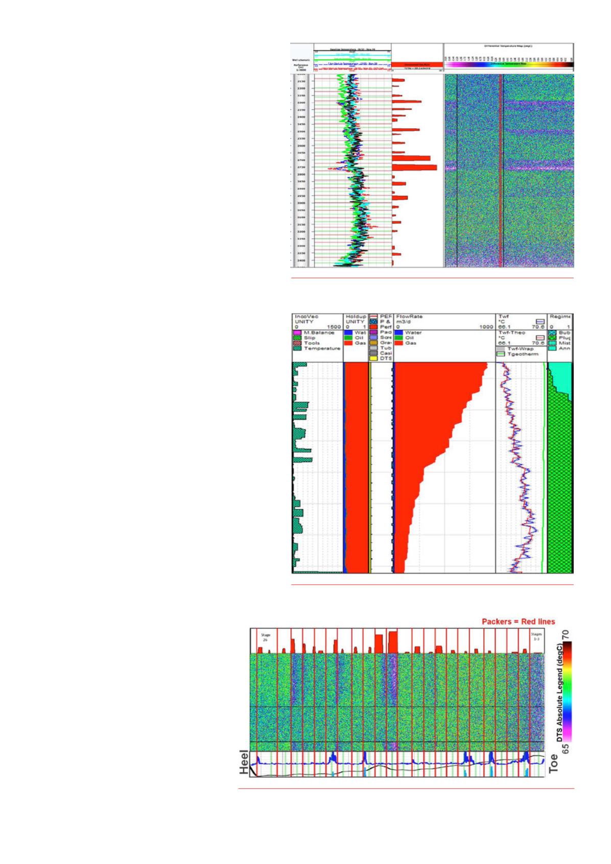
Figure 6.
RawDTS data - flowingwell.
Figure 8.
DTS differential data.
Figure 7.
PLATOproductionprofile.


