54 |
Oilfield Technology
September
2016
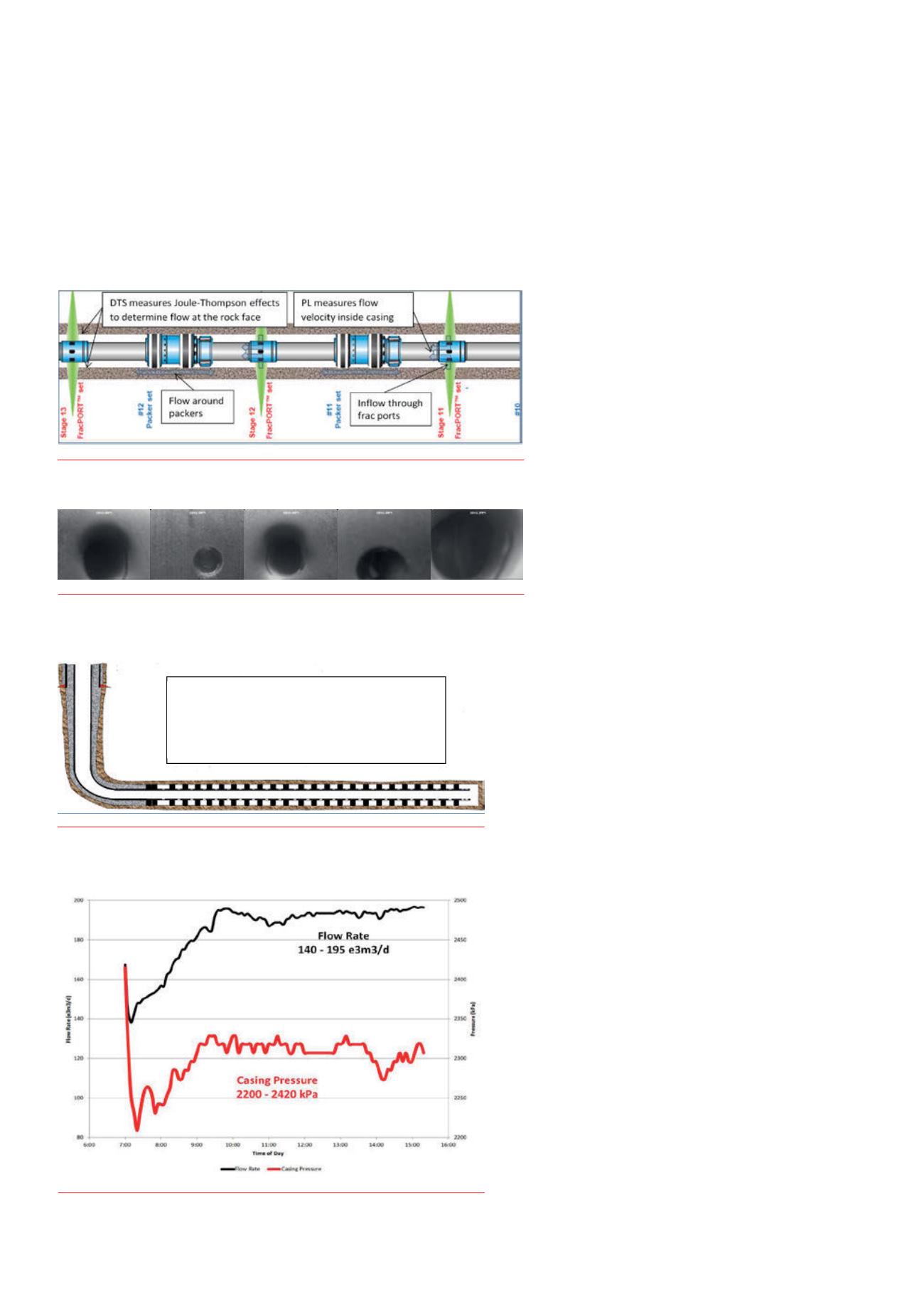
components to infer the flowdynamicswithin thewellbore. Using passive
sensingmeasurements of discrete temperature changes throughout
the entirewellbore, DTS detects floweverymeter along the rock face.
Conversely, conventional production logging tools can only detect flow
within the casing; they only see additional flowwhere it enters the casing
as shown in Figure 2.
The ability to detect flow all along the rock face is of particular
interest in openhole completions. DTS is able to pinpoint the
production along the interval between packers and detect flow around
packers. Production logging techniques can not differentiate between
production from adjacent intervals and production from the interval
that ‘should’ be flowing through a given frack port or perforation
interval, so this skews the production survey.
Zones that underperformadjacent intervals appear to produce
better than they actually do when conventional production logging
techniques are used for production profiling.
Fibre can be installed permanently, semi permanently, or run in
coiled tubing for production profiling. Permanent installations outside
the casing provide themost accurate direct measurement, however, fibre
in coiled tubing provides results that are sufficiently accurate and are
preferred to fibre strapped to production tubing that does not typically
extend to the toe of the wellbore.
Casing leakdetection
DTS can be used to locate and measure Joule-Thompson
(JT) effects of unexpected casing inflow. Conventional
techniques to locate casing leaks involve using a
microphone and moving it within the wellbore to find
the ‘noisiest’ area of the wellbore. Assuming there are no
perforations at this location, this is assumed to be the site
of the leak. Selective packer tools are often used isolate
the suspected leak spots to confirm that the leaks were
located using the acoustic technique.
In this application, the fibre can be located outside the
casing, strapped to production tubing, or run inside a coiled
tubing work string.
Stimulationoptimisation
DTS can be used to optimise various types of stimulation
treatments. The key benefit to using DTS is the ability to use
time-lapsemeasurements to visualise where the injected
fluid is going every 30 seconds andmake adjustments
on-the-fly in the field.
Matrixstimulation–diversionoptimisation
Using DTS to optimisematrix acidising has gained a significant
amount of traction in Saudi Arabia and other geographic regions over
the past five years. Numerous technical papers have been published
on the benefits of using DTS tomeasure the effects of diversion
techniques. Some case studies that have been published claim
production increases of up to eight times over prior acid stimulations.
The key benefit is that DTS can determine the effectiveness of the
diversion strategy before the acid treatment is pumped and the
diversion strategy can be adjusted accordingly. This allows new rock to
be stimulated, hence the subsequent gains in production.
In this application, the fibre can be permanently installed in the
wellbore or installed in the coiled tubing work string used for the
stimulation treatment.
Limitedentry fracks–adjust rates
Limited entry is a technique where the flow ports (perforations
or orifices) are sized to generate sufficient back pressure. This
back pressure causes the frack fluid to divert to other ports. In
ideal conditions, this results in an even distribution of stimulated
perforations. Unfortunately, no source rock is homogenous and
ideal conditions do not exist in very many oilfields. Downhole
cameras have been used to show that not all perforations in a
limited entry completion participate in the frack. Figure 3 shows
frack ports located at the same depth within a horizontal wellbore
in Western Canada. By looking at the erosion alone, it is obvious
the three of the five ports shown took fluid whereas the others
did not. On this particular frack, the pump rate was 3000 l/min
(18.87 bbls/min) through fifteen 11 mm (7/16 in.) ports.
Figure 2.
DTS versus PL comparison.
Figure 3.
Frack ports locatedat the same depthwithina horizontal wellbore inWestern
Canada.
that DTS can determine the effectiveness of the diversion strategy before the acid treatment is pumped
and the diversion strategy can be adjusted accordingly. This allows new rock to be stimulated, hence the
subsequent gains in production.
In this application, the fiber can be permanently installed in the wellbore or installed in the coiled tubing
work string used for the stimulation treatment.
Limited entry fracs – adjust rates
Limited entry is a technique where the flow ports (perforations or orifices) are sized to generate
sufficient back pressure. This back pressure causes the frac fluid to divert to other ports. In ideal
conditions, this results in an even distribution of stimulated perforations. Unfortunately, no wellbore is
ideal and ideal conditions do not exist in very many oil fields. Downhole cameras have been used to
show that not all perforations in a limited entry completion participate in the frac. Figure 5 to Figure 9
show 5 frac ports located at the same depth within a horizontal wellbore in Western Canada. By looking
at the erosion alon , it is obvious the 3 of the 5 ports shown took fluid whereas the others did not. On
this particular frac, the pump rate was 3000 L/min (18.87 bbls/min) through 15 11mm (7/16”) ports.
Figure 5 - Frac Port
Figure 6 - Frac Port
Figure 7 - Frac Port
Figure 8 - Frac Port
Figure 9 - Frac Port
DTS can be used to optimize limited entry fracs. By monitoring frac placement in real time, flow rates
can be increased to ensure that every perforation cluster is active, provided sufficient pumping
horsepower is present on location. Refracturing operations on existing wells benefit similarly because
‘thief zones’ can be identified immediately and corrective actions can be taken to divert the treatment
to other zones.
For limited entry frac optimization, fiber is ideally permanently installed in the wellbore, outside the
casing. It is not usually practical to have a coiled tubing string inside the wellbore during fracturing
operations unless the coiled tubing is being used as the conduit to place the frac.
At a recent distributed sensing workshop, an operator using DTS for limited entry frac
optimization reported that their key learning was that they needed to get much more aggressive
with pump rates or reduce the number of perforations in their limited entry completions.
Case Study - Production Profiling
Objective – develop a better understanding of inconsistent well to well production
The operator has an active field co sisting of several wells on pads in a particular play in Western
Canada. Each of these wells has varying levels of production even though the formation is considered to
be fairly homogeneous. One well in particular is a significantly better producer than the others in the
field. Knowing how this well was completed and understanding that every stage doesn’t contribute to
production equally, the hope was to learn what went ‘right’ with this well and apply it to other wells in
the area on future completions.
The operator’s key objectives were:
1.
Determine where within the wellbore the production is coming from (production profile).
2.
Measure the effectivene s of the fracture stages in the horizontal lateral.
3.
Dete min which parameter(s) (Gas ratio, Gas Counts, Total Organic Content, Frac Tonnage, Frac
Rate, etc.) correlated with the best producing stages of a top producing well.
4.
Determine the production profile after ~50% estimated ultimate recovery (EUR).
Well Details
The well was completed according to standard Western Canadian horizontal well completion practices
using a 26 stage ball drop – open hole system as shown below in Figure 10. 55 tonnes of sand was
placed into each zone using a slickwater fluid system. The amount of fluid in the pad used to initiate the
fr cs did change from zone to zone but otherwi e th frac program was consistent for all 26 intervals.
Figure 10 - Well Completion
Production Survey
This well had been on production
Fiber Deployment
A 5800m (19,000’) long 60.3mm (2-3/8”) coiled tubing string containing an electrical conductor, single-
mode and multi-mode fiber optic cable was dispatched to location. Only the multi-mode fiber as used
for the DTS survey on this job however this string is capable of being used for DAS and with conventional
logging tools. The coiled tubing conveyance string can be used for conventional coiled tubing
applications, even during distributed sensing surveys.
•
Casing: 114.3mm (4.5”)
•
3589m (11775’) total measured depth
•
1914m (6280’) t tal ve tical depth
•
26 P ckers Plus B ll Drop Frac Stages
Figure 4.
Well completion.
Figure 5.
Pressure and flow rate duringDTS survey.


