


 40 / 56

38 |
Oilfield Technology
May/June 2020
Prior to commencement of well control operations, a significant
amount of dredging had to be completed to provide barge access to
the well, as the waterway leading to the rig was too shallow otherwise.
Initialwellheadassessment
Ignited flow could be observed escaping from the side outlet valve on
the B-section of the wellhead (2 7/8 in. tubing x 9 5/8 in. casing), sending
a strong hydrocarbon stream upwards and outwards, and to a lesser
extent downwards. Minor leaks were observed between the top of the
B section and the tree, and also near the top of the upper master valve.
It was unknown at the time whether the plugs in the tubing or any of
the packers had failed, which would have led to either an annular leak
path through a damaged packer or through a more complex route
involving tubing leaks.
Interventionstrategy
As several barriers had been installed in the tubing, it was determined
that annular flow through a damaged packer was the means by which
the hydrocarbons were leaking. It became clear that the initial thrust of
the recovery operations would entail tree removal.
After removing the lower flange of the B section, the upper
13 5/8 in. wellhead flange condition could be inspected. The subsequent
sequence of steps to control the well would ultimately depend on the
results of the inspection. If the existing wellhead flange was found to
be damaged, the entire wellhead would have to be cut off to allow
re-heading. Unfortunately, re-heading would require the installation
of a coffer dam because the wellhead was below the water level at
high tide.
If the existing wellhead flange was found to be serviceable
however, capping could be performed on the existing flange using a
capping stack.
A third option for well control was to use a relief well to stop the
flow of hydrocarbons.
Mobilisationofpersonnel andequipment
Boots & Coots specialists were initially dispatched to the operator’s
base to help generate planning documents and to liaise with company
personnel working from the operator’s camp to guide preparations and
coordinate planning with the operator’s office.
Coordination of the sourcing and mobilisation of specialised
firefighting equipment available in-country was also carried out.
Firefighting equipment, including an abrasive jet cutter available
in-country, were transported to the dock facilities and loaded onto
the barges for transportation to the staging location. On arrival, the
equipment was reassembled, tied down and tested prior to being
transported to the field. The equipment included:
Ì
A pumping barge.
Ì
A firefighting barge.
Ì
An Athey wagon barge.
Ì
A crane barge.
Ì
A spare barge.
Ì
A lube and bleed barge.
Additional firefighting equipment was mobilised fromHouston to
ensure sufficient backup was available.
Sitepreparation
Extensive dredging was required to facilitate work barge access to the
well area. The prevailing wind direction was from the southwest and
carried gas and residue across the canal entry and across the main
canal towards the local communities. Available barges were sourced
and modified to suit the planned operations and the operator was also
assisted in procuring the required heavy equipment and materials,
using knowledge of in-country vendors.
The logistical challenges of maintaining operational support
routes, continuous fuel provision, and security concerns were dealt
with on a daily basis. Tidal influences within the well estuary limited
the ability to conduct necessary civil work, as the outgoing tide
pulled surface oil back towards the canal, creating an impassable
burning curtain. After four weeks, the well began to produce water
in sufficient amounts to temporarily extinguish the well fire. With
each extinguishment event, the well flowed significant amounts of
Figure 1.
Riverside fishing communities along the estuary access to the
wellsite.
Figure 2.
Hydrocarbons spillingalong the estuary fromthe blowout well
and spontaneously igniting.
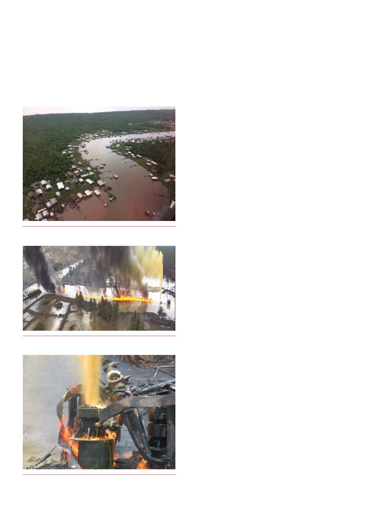
Figure 3.
Well blowing vertically.