


 41 / 56

May/June 2020
Oilfield Technology
|
39
combustible oil onto the water surface and into the surrounding
vegetation. This created significantly larger surface fires each time the
well spontaneously reignited.
Shallow dredging to expedite access to the well resulted in barges
and work boats being stranded and exposed to surface oil fires due to
changes of wind direction.
Well control operations
Structural members of the well jacket initially limited access to the
wellhead. Consequently, vertical members on the northwest and
northeast corners of the well jacket and a horizontal member of the
jacket that were blocking access from the north side of the well were
targeted for removal by the abrasive jet cutter.
The Athey wagon barge was equipped with the rake attachment to
attempt removal of these structural members. The firefighting barge
was spotted on the west side of the slot to allow the Athey wagon barge
to move into the well on the east side of the slot. In the event, the tree
could not be pulled away by the rake, which meant it had to be cut
off using an abrasive jet cutter. Water monitors sprayed the wellhead
to suppress the fire and heat, allowing the well control specialists
to approach the well and assess and identify which structural
components of the well jacket would have to be removed in order to
enable the jet cutter to carry out the cutting operation.
Wind and tide conditions delayed several efforts to remove
additional debris; a total of six cuts were made by Boots & Coots, using
an Oxylance and an acetylene torch, to remove additional debris from
the northwest side of the well jacket in preparation for removal of the
lower B section flange and well capping.
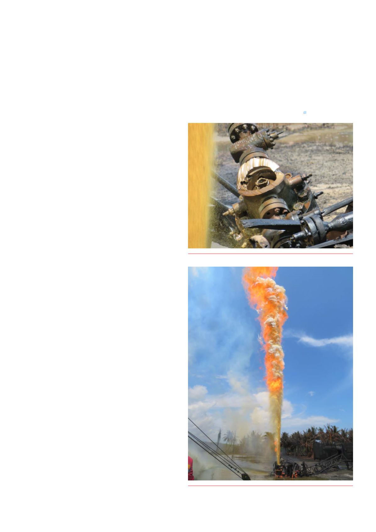
The abrasive jet cutter successfully removed the tree at the
B section, leaving the 13 5/8 in. lower flange of the B section still
attached to the upper flange of the wellhead (A section).
Using fire cannon water spray, the abrasive jet cutter was used to
cut the tree off as planned, resulting in a single vertical flow from the
well (Figure 3).
Close inspection of the 13 5/8 in. wellhead flange condition
indicated it was still in good enough condition and that capping could
be performed (Figure 4).
The action of removing the tree prevented the lateral extension of
the fire and greatly improved both visibility and safety by directing the
flame upwards (Figure 5).
A venturi tube was installed above the casing head to direct the fire
vertically and away from the area while working on preparations for
the installation of the capping stack.
Cappingstack:designandassembly
The company designed and constructed a capping stack using blowout
preventer (BOP) equipment available from the operator and in-country
resources. The stack was assembled, tested, and transported on a
barge to the well staging area. A yoke was designed and constructed to
support the stack using the Athey wagon boom, in order to deploy the
capping stack onto the well. Inclement weather and tidal conditions
delayed the proposed capping operations for a number of days as
approximately 10 daylight hours of favourable tides and wind direction
was required. At this point, the operator decided to continue the
capping operation with its own personnel.
Importantly, difficulty in sourcing the necessary double-studded
adaptors resulted in the use of a modified B section to cross over from
13 5/8 in. 3M to 11 in. 5M at the bottom of the capping stack.
Summary
The well was successfully addressed through a coordinated project
that used a number of barges in a particularly difficult environment.
Although much of the equipment required could be mobilised
in-country, significant time had to be dedicated to both sourcing
the necessary vessels to transport the equipment and the dredging
operation to gain access to the rig site. The particularly challenging
operation of debris clearance – in order to gain access to the
wellhead – took considerable time, but was safely and successfully
accomplished, as was the planning and cutting of the wellhead in
preparation for the newly engineered capping stack.
Despite adverse weather conditions, the remoteness of the
location leading to a myriad of logistical challenges, and a dynamically
changing situation, the operation was conducted safely with no lost
time incidents during the wellhead remediation.
Figure 4.
Bottomof cut onB section.
Figure 5.
Removal of the tree achieveda single vertical flow.