32 |
Oilfield Technology
September
2016
depths (TVD). Therefore, an extra length of the well creates
added frictional pressure along the lateral while TVD increases
insignificantly, i.e. does not gain as much formation integrity
with depth. Thus, looking back at the ECD formula, it is clear that
with increasing ∆P and relatively constant TVD, ECD will increase
(Figure 2).
Another concern is that ERD wells with long intervals are prone
to fatigue failures over time with constantly cycling pumps on
and off. Also, ERD well designs often necessitate the use of larger
OD pipe for buckling resistance and improved hydraulics. This
inadvertently leads to higher ECD.
Additional complications with ECD management in ERD wells
come from balancing critical but opposing design parameters
specific to ERD wells execution that is critical to success (i.e. good
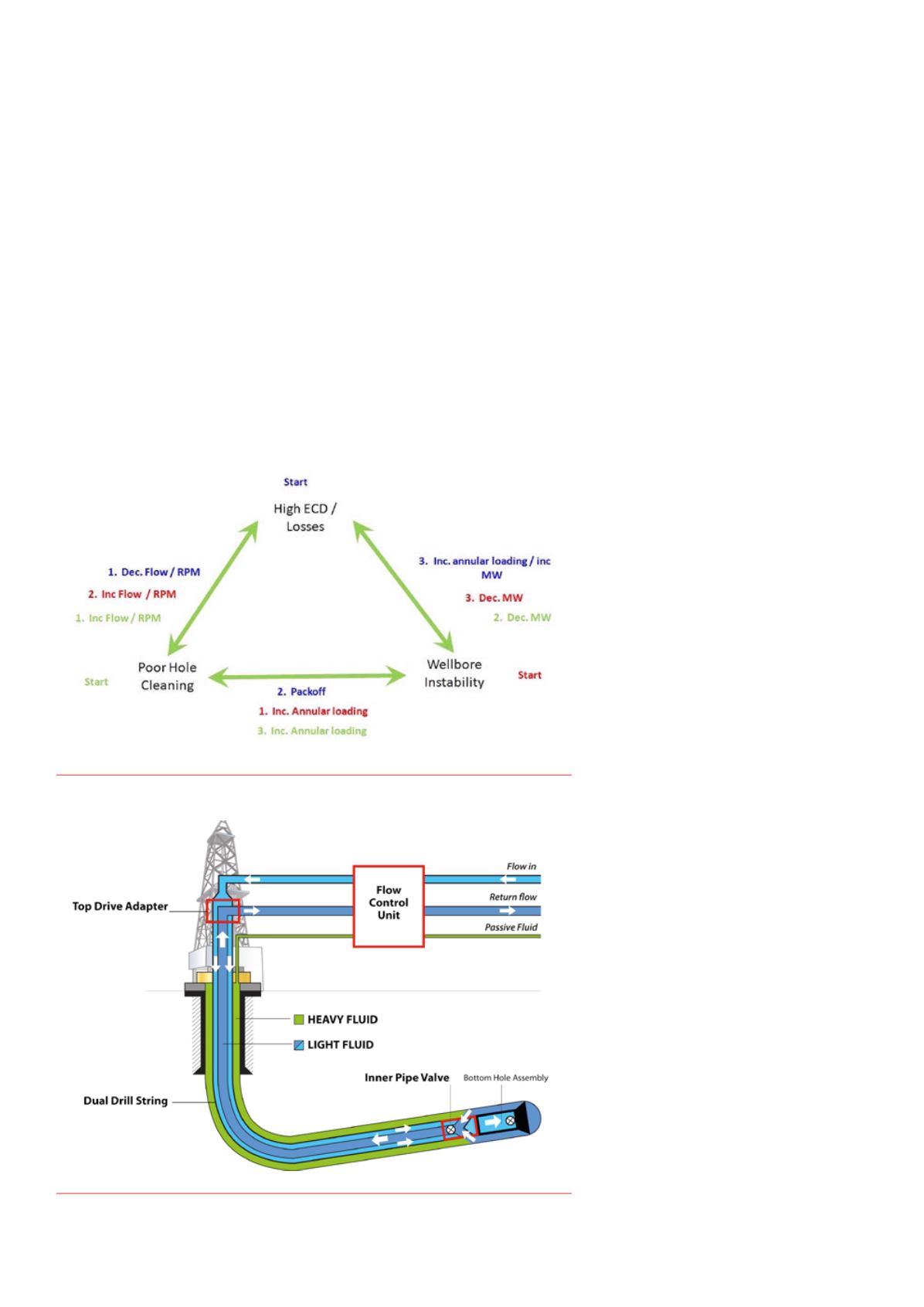
hole cleaning vs. ECD management). That is the so-called ‘vicious
cycle’ from which it is hard to escape (Figure 3).
There are two major stages of ECD management – planning and
operational.
Operators often succumb to the pitfalls of using ‘off-the-shelf’
equipment and even worse, the equipment that the rig came with
– whether it is drill pipe and connection types, surface equipment
limits, mud pumps, solids control equipment, electrical supply
capacity, etc. However, drilling an extended reach well is already
a non-standard operation by definition, and operators must use
fit-for-purpose equipment.
A lot of operators attempt to take shortcuts to minimise the
cost of an ERD well by using standard equipment but often end up
paying a very high price for train wrecks. Instead, before drilling
an ERD well, a feasibility study and a cost/benefit analysis must
be performed to understand the real value of such an asset. This
approach will eliminate taking shortcuts for cost savings, facilitate
using fit-for-purpose equipment and ultimate success of an ERD
well. Thus many challenges of drilling an ERD well, including ECD
issues, can be addressed at the planning stage; it is the most
effective mitigation strategy.
Planningstagemitigators
Well profile
The wellbore trajectory has major implications to total measured
depth to be drilled, hence drives annular frictional pressure loss,
true vertical depth that helps to counteract ECD issues (higher
competency formation), casing design, mud
weight programme, casing and drill pipe wear,
geological uncertainty, etc.
Some well profiles due to wellbore stability
reasons require higher MW, which will in turn,
increase ECD. Generally, it is desirable to
choose a profile that has the shortest path
to the target. This is often very challenging
to achieve as other design parameters must
be satisfied (buckling, casing design, hole
cleaning, wellbore stability, torque and drag,
etc.) – therefore it is, again, a risk balancing
act.
Well design
Hole sizes
Common sizes for ERD wells globally are
considered to be 17 ½ in., 12 ¼ in., 8 ½ in. and
6 in. However, often alternative sizes such as
6 ¾ in. instead of 6 in., 9
7
/8
in. or 8 ¾ in. instead
of 8 ½ in. are used.
One might think that such minor
changes in hole sizes may not make a
significant difference. However after taking
into consideration drill pipe tool joints and
casing ODs, annular cross sections can be
increased dramatically, thus decreasing ECD
substantially. If hole sizes are increased,
considerations should be given to the effects
on hole cleaning efficiency.
Other alternatives are under-reaming and
using bi-centred bits to enlarge the hole size to
aid in increasing annular clearance.
Casingprogramme
One of the options in modifying the casing
programme for improving ECD management
is using lighter weight casing (i.e. thinner wall,
larger ID); this can have a significant impact
when drilling reservoir sections through very
long intermediate casing strings. For instance,
Figure 3.
Interdependency of hole cleaning, wellbore instability and ECDmanagement.
Figure 4.
Schematic of the RDMsystemset up.


